I-2533CS
I-2533CS
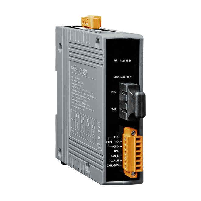
CAN to Single-mode Fiber Bridge
Features
- Fiber Type: SC ; Single mode ; 100 Base-FX
- Maximum transmission distance up to 30 km at any CAN baud rate
- NXP TJA1042 CAN transceiver
- 2500 Vrms isolation on the CAN side
- Supports both CAN 2.0A and CAN 2.0B
- Fully compatible with the ISO 11898-2 standard
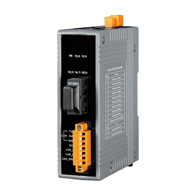
- Rotary switch for CAN baud rate configuration
- Build-in switch for 120 Ω terminal resistor
- Removable terminal block, Mount easily on DIN-Rail
- Allows user-defined CAN baud rate
- Fiber broken line detection
- Utility tool for CAN message filter configuration
- The CAN port with the same Group ID can communicate with each other
- Introduction
- Application
- Specification
- Download
- Get A Quote
Introduction
The I-2533CS is a local CAN bridge used to establish a connection between two CAN bus system via single mode fiber optic transmission medium. In order to solve the problem between CAN and fiber transmission medium, the I-2533CS is specially designed for converting the electrical CAN bus signal to fiber optic cables. I-2533CS has three more important features. First, the transmission distance limitation of the CAN bus system will not affected due to the different CAN baud rate. It means that the total CAN bus working distance can be extended. Second, the bus error on one CAN network will not affect the operation of another CAN network. Finally, the two CAN network can communication with each other by using different CAN baud rate for highly flexibility.
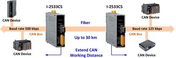
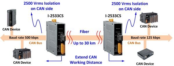
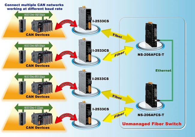
The I-2533CS series is designed for single mode fiber, and allow to extern CAN bus to maximum 30 km. Besides, I-2533CS provides the group function, which is the basic message router. Users can decide the CAN message flows between several CAN bus systems. I-2533CS series also provides the utility tool for user-defined baud rate and filter configuration. By using this tool, it is allowed to have user-defined baud rate and CAN message filter. When users use the I-2533CS series on two CAN network with different CAN baud rate, it may be useful to reduce the bus loading of the network which has low baud rate.
| Fiber Converter | ||||||||
|---|---|---|---|---|---|---|---|---|
| Module Name | I-2533CS-FD | I-2533T-FD | I-2533CS | I-2533CS-60 | I-2533CS-A * | I-2533 | ||
| I-2533CS-B * | I-2533-UTA | |||||||
| CAN Interface | ||||||||
| Module Type |  |
|
|
|
|
|
||
| Baud Rate (bps) | CAN: 10 ~ 1000 kbps FD: 100 ~ 10000 kbps |
10k ~ 1M (user-defined) | ||||||
| CAN Filter | Yes | |||||||
| 120Ω Terminal Resistor | Built-in | |||||||
| Isolation | 3000 VDC (DC-DC), 2500 Vrms (photo-coupler) | |||||||
| Specification | ISO 11898-2, CAN 2.0A/B, CAN FD | ISO 11898-2, CAN 2.0A / 2.0B | ||||||
| Propagation Delay | 190 μs ** | 250 μs ** | ||||||
| Fiber Interface | ||||||||
| Type | SC Duplex, Single-mode, 100Base-FX | ST Duplex, Multi-mode, 100Base-FX | SC Duplex, Single-mode, 100Base-FX | SC, Single-mode, 100Base-FX | ST (Multi-mode) | |||
| Wavelength (nm) | 1310 | TX 1310 / RX 1550 (A) TX 1550 / RX 1310 (B) |
850 | |||||
| Fiber Cable (μm) | Single-mode | Multi-mode | Single-mode | Multi-mode | ||||
| Max Distance | 30 km | 2 km | 30 km | 60 km | 15 km | 2 km | ||
| Miscellaneous | ||||||||
| Topology | One-to-One / One-to-Many | One-to-One | ||||||
| Work with Fiber Switch | Yes | No | ||||||
| Extend CAN Distance | Yes | |||||||
| Repeat CAN Signal | Yes | |||||||
| Network Integration | Yes | |||||||
|
* Note 1: I-2533CS-A and I-2533CS-B must be used in pairs. ** Note 2: Propagation delay depends on CAN baud rate and message format. |
||||||||
Application
Specification
| LED Indicators | |
|---|---|
| Status |
1 x Power 3 x CAN status 2 x Fiber status |
| COM Ports | |
|---|---|
| Ports | 1 x RS-232 (Utility Port) |
| Fiber | |
|---|---|
| Ports | Single-Mode; SC Duplex connector x 1; 100 Base-FX |
| Fiber Cable | 8.3/125, 8.7/125, 9/125 or 10/125 μm |
| Wavelength | 1310 nm |
| TX Output | -15 dBm Min., -8 dBm Max. |
| Transmission Distance | 30 km (9/125 μm recommended) |
| RX Sensitivity | -34 dBm Max. |
| RX Overload | -5 dBm Max. |
| Budget | 19 dBm |
| Propagation Delay | 190 µs (*Note1) |
| CAN | |
|---|---|
| Ports | 1 |
| Specification | ISO 11898-2, CAN 2.0A and CAN 2.0B |
| Baud Rate | 10 k ~ 1 M bps |
| Isolation | 500 Vrms on the CAN side |
| Terminal Resistor | Switch for 120 Ω terminal resistor |
| Filter | Yes |
| Power | |
|---|---|
| Input Range | +10 VDC ~ +30 VDC |
| Consumption | 3 W |
| Mechanical | |
|---|---|
| Casing | Plastic |
| Dimensions (mm) | 33 x 126 x 101 (W x L x H) |
| Installation | DIN-Rail |
| Environment | |
|---|---|
| Operating Temperature | -25 ~ +75 °C |
| Storage Temperature | -30 ~ +80 °C |
| Humidity | 10 ~ 90% RH, Non-condensing |
Download
